EASTLIFT
Product description
Working Principle of Intelligent Sensing Early Warning & Protection System for Diesel Rough-Terrain Scissor Lifts (RT Scissor Lifts)
The complete system consists of multi-type perception sensors, vehicle-mounted main ECU controller, graded audible and visual alarm devices, as well as hydraulic/travel executive protection mechanisms. Targeting six major hazards on rugged construction sites including uneven ground, soft foundation, overloading & eccentric loading, overhead collision, side impact and outrigger instability, it forms a closed-loop protection workflow: real-time data acquisition → multi-source data fusion → graded early warning → active motion restriction / forced shutdown. The system adapts to harsh off-road working conditions such as mountain photovoltaic projects, muddy road and bridge construction sites.
I. System Hardware Composition (Exclusive Sensor Layout for Rough-Terrain Scissor Lifts)
1. Attitude Stability Sensors (Core Anti-Tip Over Protection, Critical for Off-Road Operation)
- Dual-Axis Chassis Inclinometer (Fixed on Vehicle Frame)
It continuously collects longitudinal and lateral tilt angles of the whole machine to distinguish slopes, soft foundation settlement and suspended outriggers ("soft legs"). Industry safety thresholds:
- When overall tilt angle exceeds 3°, Level 1 alarm is triggered;
- When tilt angle exceeds 5°, lifting and travel power are cut off.
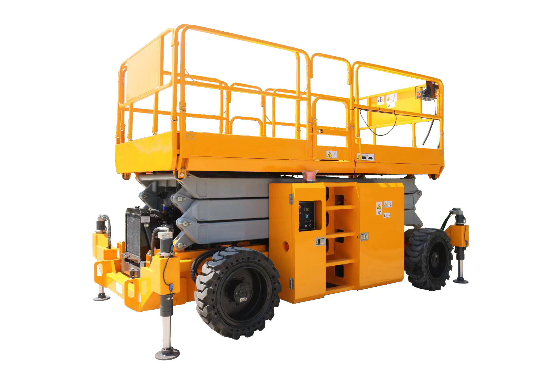
- Composite Sensors for Stroke & Pressure of Four Outriggers
Each outrigger is equipped with a proximity switch for full extension detection and a pressure sensor on the outrigger cylinder:
- Detect whether the outrigger fully contacts the ground and identify suspended conditions caused by soft soil subsidence (soft legs);
- If the pressure of any single outrigger drops below the safety threshold, the system judges supporting failure and prohibits lifting operations.
- Scissor Arm Angle Encoder (Lifting Height Measurement) It outputs the opening angle of scissor arms in real time to convert into working height. The higher the platform rises, the narrower the stability threshold of the whole machine — smaller allowable tilt angle and lower allowable load at elevated heights. The system dynamically limits the rated load and permissible slope gradient accordingly.
- Platform Cabin Inclinometer Monitors local tilt of the platform induced by personnel or materials with eccentric weight, preventing side tipping caused by unilateral overload.
2. Load Safety Sensors (Overload & Eccentric Load Protection)
High-pressure sensor on lifting cylinder
It measures hydraulic pressure inside the rodless chamber of the lifting cylinder continuously. Combined with scissor arm height and chassis tilt angle, the ECU dynamically calculates the maximum allowable load corresponding to the current height — the rated load decreases linearly as the lifting height rises:
- Minor overload: Yellow light with intermittent buzzer warning;
- Severe overload: Lifting motion locked, only platform lowering for pressure relief is permitted.
3. Obstacle Detection Sensors (Anti-Overhead-Impact & Anti-Side-Squeeze Protection)
High-end units are standard-fitted with millimeter-wave radar, ultrasonic radar and top laser rangefinder:
- Top-mounted radar: Detects overhead scaffolding, beams and bridge frames to avoid overhead collision;
- Perimeter radar around platform: Detects walls, steel structures and surrounding personnel to prevent lateral squeezing hazards;
- The system automatically raises the detection threshold under off-road mode to filter false triggers from ground gravel and weeds.
4. Diesel-Exclusive Power & Hydraulic Fault Sensors
- Engine sensors: Coolant temperature, engine oil pressure, exhaust temperature;
- Hydraulic system sensors: Hydraulic oil temperature, pipeline pressure, position feedback of explosion-proof valves;
- Emergency stop circuit, Hall sensors on control levers (to prevent misoperation).
5. Executive Output Components
Vehicle-mounted ECU, tri-color audible & visual alarm lamp (yellow for warning / red for danger), voice buzzer, hydraulic proportional valve cut-off module, travel brake solenoid valve, explosion-proof lowering lock valve.
II. Complete Working Logic: Four-Stage Closed-Loop Protection Process
Stage 1: Full-Scope Real-Time Data Acquisition (Millisecond Synchronization)
All sensors transmit analog and digital signals to the main ECU continuously. The ECU conducts multi-source data fusion to eliminate false alarms generated by single sensor drift:
- Example: Excessive chassis tilt + sharp pressure drop on one side outrigger → System confirms soft leg caused by ground subsidence instead of sensor failure;
- Example: Rising cylinder pressure + increased scissor arm opening angle → System identifies high-altitude overload, excluding transient hydraulic pressure impact interference.
Stage 2: Comprehensive Judgment via Safety Model (Off-Road Adaptive Algorithm)
The ECU embeds a dedicated stability calculation model for rough-terrain scissor lifts, which simultaneously calculates four core safety indicators:
- Lateral & longitudinal tilt of chassis
- Support balance of four outriggers
- Rated allowable load matching current lifting height
- Platform eccentric load and distance to surrounding obstacles
- A stability coefficient K is generated automatically:
- K > 1.5: Fully safe, all machine motions unrestricted;
- 1.2 ≤ K ≤ 1.5: Critical risk, Level 1 early warning activated;
- K < 1.2: High tipping risk, Level 2 forced power restriction enabled.
Stage 3: Graded Early Warning Mechanism (Three-Tier Protection Without Hasty Shutdown)
Level 1 Early Warning (Steady Yellow Light + Intermittent Buzz, Prompt for Rectification)
Trigger scenarios:
Chassis tilt between 2°~3°, minor overload, obstacles entering 5m pre-warning zone, incompletely extended outriggers, slightly overheated engine coolant.
Motion restriction: No full motion lock, continuous reminder only; minor adjustments of outriggers, load removal or chassis leveling movement are allowed.
Level 2 Warning (Flashing Red Light + Continuous High-Frequency Buzz, Mandatory Motion Restriction)
Trigger scenarios:
Chassis tilt between 3°~5°, overload of 10%~20%, obstacles entering 2m danger zone, slight suspension of single outrigger.
Motion restriction: Lifting and high-speed travel prohibited; only platform lowering, outrigger retraction and low-speed leveling movement are available to avoid heightening tipping risks.
Level 3 High-Risk Protection (Steady Red Light + Continuous Long Buzz, Hazardous Power Cutoff)
Trigger scenarios:
Chassis tilt ≥5°, overload exceeding 20%, obstacles in direct contact with platform, two or more suspended outriggers, hydraulic pipe rupture & pressure loss, engine malfunctions.
Motion restrictions:
- Power supply for lifting, forward and reverse travel cut off immediately;
- Explosion-proof hydraulic valves lock cylinders to prevent rapid platform descent;
- Only safe actions including platform pressure relief lowering and outrigger retraction are retained;
- High engine RPM output limited under certain working conditions for diesel units.
Stage 4: Fault Reset Logic
After operators complete rectification (load removal, outrigger leveling, relocation to flat ground, clearance from obstacles), sensor readings return to safe ranges, alarms clear automatically and full machine motion authority restores. If high-risk status persists for over 30 seconds, the system locks the machine, which requires exiting the platform and restarting for reset.
III. Unique Sensing Protection Logic of Rough-Terrain Scissor Lifts vs. Electric Scissor Lifts
1. Specialized Soft Foundation "Soft Leg" Protection
Standard electric scissor lifts only adopt proximity switches to detect outrigger full extension. Diesel RT scissor lifts add outrigger pressure sensors. Immediate alarms activate once unbalanced outrigger loads occur on muddy, gravel or mountain photovoltaic slopes, addressing the most common tipping cause at construction sites.
2. Dynamic Load Derating on Sloped Ground
For every additional 1° of chassis tilt, the ECU automatically reduces the rated load capacity. For instance, a unit rated for 500kg on flat ground only permits 300kg load when elevated on a 3° slope, fundamentally limiting outward shift of the center of gravity.
3. Interlocked Travel Restriction Based on Platform Attitude
When the platform lifts higher than 3 meters, the system caps travel speed at ≤3km/h. If tilt exceeds the threshold, travel function locks entirely to prevent sliding while climbing slopes with load.
4. Linked Protection for Diesel Power Malfunctions
In cases of low engine oil pressure, overheated coolant or excessive exhaust temperature, the system simultaneously restricts heavy-load lifting operations, avoiding platform runaway hazards caused by engine stall under high temperature.